


Please Leave Us A Message
Privacy statement: Your privacy is very important to Us. Our company promises not to disclose your personal information to any external company with out your explicit permission.
 April 22, 2019
Filter circuit
Although the rectifier circuit can convert the alternating current into direct current, the pulsation component is large, and it is not applicable in some cases where the direct current is required to be smooth. A filter circuit is needed to reduce the pulsating component in the rectified direct current.
The magnitude of the pulsating component in general direct current is expressed by the pulsation coefficient:
Pulsation coefficient (S) =

GS0712
For example, the full-wave rectified output voltage uL can be expanded by the Fourier series:

The fundamental value is 0.6U2, and the DC component (average value) is 0.9 U2, so the ripple coefficient is ≈0.67. Similarly, the pulsation coefficient of the half-wave rectified output voltage is S=1.57, and the pulsation coefficient is relatively large. Generally, the pulsation coefficient of the DC power supply required by the electronic equipment is less than 0.01, so the voltage of the rectified output must take certain measures. On the one hand, the pulsating component in the output voltage is minimized, and on the other hand, the DC component in the output voltage is saved as much as possible to make the output voltage Close to the output voltage of a preferred DC power supply. This measure is filtering.
The most basic filter components are inductors and capacitors. The filtering principle is: using these reactance components to store energy during the conduction of the rectifier diode and release energy during the off period, so that the output voltage becomes relatively smooth; or from another point of view, the capacitance and inductance are opposite to the AC component. The reflected impedances are different, and they are reasonably arranged in the circuit to achieve the purpose of reducing the AC component while preserving the DC component, and exhibiting the filtering effect.
Commonly used filter circuits are passive filtering and active filtering. The main forms of passive filtering include capacitive filtering, inductive filtering and complex filtering (including inverted L-type LC filtering, π-type LC filtering and π-type RC filtering, etc.). The main form of active filtering is active RC filtering.
Capacitor filtering
The half-wave rectification capacitor filter circuit is shown in Figure Z0710. The filtering principle is as follows:

Capacitor C is connected in parallel across the load RL, uL = uC. Before the capacitor C is incorporated, the rectifier diode is turned on during the positive half cycle of u2, and the negative half cycle is turned off. The waveform of the output voltage uL is shown by the red line in the figure. After the capacitor is incorporated, the power supply is turned on when ωt=0. When u2 is gradually increased from zero, the diode D is turned on. In addition to a current iL flowing to the load, a current iC is charged to the capacitor C, and the charging voltage uC is charged. The polarity is positive and negative.
If the internal resistance of the diode is ignored, the uC can be charged to a peak u2m close to u2. After u2 reaches the maximum value, it begins to fall, and at this time, the voltage uc on the capacitor will also gradually drop due to the discharge. When u2

The principle of full-wave or bridge-type rectifying capacitor filtering is basically the same as that of half-wave whole-wavelength capacitor filtering. The filtering waveform is shown in Figure Z0711.
From the above analysis, we can see:
1. After capacitive filtering, the DC component of the output voltage is increased and the pulsating component is reduced. This is due to the energy storage of the capacitor. The capacitor charges (storage) when the diode is on, and discharges (releases energy to the load) when turned off, which not only increases the average value of the output voltage, but also makes it smoother.
2. The larger the discharge time constant (τ = RLC) of the capacitor, the slower the discharge, the higher the output voltage, and the less the pulsation component, that is, the better the filtering effect. Therefore, the value of C is generally larger, and RL is also required to be larger. In practice, the value of C is often selected as follows:
RLC ≥ (3 ~ 5 > T (half wave) GS0714
RLC≥(3~5)T/2 (full wave, bridge type) GS0715
3. The conduction time of the rectifier diode in the capacitor filter circuit is shortened, that is, the conduction angle is less than 180°. Moreover, the larger the discharge time constant, the smaller the conduction angle. Therefore, the rectifier diode flows through a large inrush current, which is detrimental to the life of the tube. When selecting a diode, a large margin must be left.
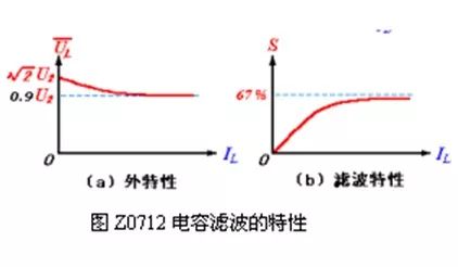
4. The external characteristics of the capacitor filter circuit (referring to the relationship between UL and IL) and the pulsation characteristics (the relationship between S and IL) are relatively poor, as shown in Figure Z0712. It can be seen that the output voltage UL and the ripple coefficient S vary with the change of the output current IL. When IL = 0 (ie RL = ∞), UL = U2 (the capacitor is no longer discharged after charging to the maximum value), S = 0.
When IL increases (ie, RL decreases), UL decreases due to an increase in the degree of discharge of the capacitor, and the range of UL varies between U2 and 0.9 U2 (refers to full-wave or bridge), and S becomes larger. Therefore, capacitive filtering is generally suitable for applications where the load current does not change much.
5. The calculation of the output voltage of the capacitor filter circuit. If the discharge time constant of the capacitor filter circuit is based on the value of GS0714 or GS0715, the output voltages are:
UL=(0.9~1.0)U2 (half wave) GS0716
UL=(1.1~1.2)U2 (full wave) GS0717
The capacitor filter circuit has the advantages of simple structure, convenient use and wide application.
The above is the Capacitor filter circuit, principle of full-wave or bridge rectifier capacitor filtering we have listed for you. You can submit the following form to obtain more industry information we provide for you.
You can visit our website or contact us, and we will provide the latest consultation and solutions
Send Inquiry
Most Popular
lastest New
Send Inquiry
Send Inquiry

Mr. JOHN CHANG
Tel:86-514-87782298
Fax:86-514-87782297
Mobile Phone:+8613375278321
Email:info@stt.tm
Address: 3rd Floor, Weiheng Building No.20 B Area, Yangzhou, Jiangsu,China, Yangzhou, Jiangsu
Related Products List
Mobile Site

Privacy statement: Your privacy is very important to Us. Our company promises not to disclose your personal information to any external company with out your explicit permission.
Fill in more information so that we can get in touch with you faster
Privacy statement: Your privacy is very important to Us. Our company promises not to disclose your personal information to any external company with out your explicit permission.