1. Introduction It is of utmost importance whether the main equipment transformer (abbreviation: main transformer) operating in the power system is safe and stable. Monitoring the main transformer temperature is an important measure of its real-time operating conditions and safe operation, and it is also one of the important conditions for realizing an unattended operation of an integrated automation substation (abbreviation: self-contained station). However, the main problem in realizing the unattended operation of the self-separation station is the anomaly of the main transformer temperature information in the information-to-point operation. therefore. Based on the temperature measurement system of the main transformer of the comprehensive self-station, the abnormal phenomenon of the temperature measurement system is studied in detail and related solutions are given.
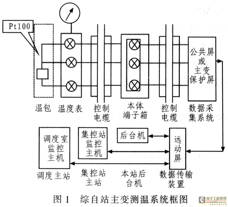
2. Introduction of the main transformer temperature measurement system of the self-separated station 2.1 Structure and principle of the self-station main transformer temperature measurement system The self-station main transformer temperature measurement system consists of the body temperature package, capillary, thermometer, temperature transmitter and channel cable. , Remote temperature tester, signal acquisition and conversion module, information transmission device (far-motivator), communication device, optical fiber cable, monitoring system host (substation comprehensive self-backstage machine, centralized control station centralized control host, dispatch centralized control host), etc. Net 1 shows. This system adopts BWY (WTYK)-803 and (TH) 802AXMT pressure type temperature indication controller (abbreviation: thermostat) with composite temperature sensor technology, which can simultaneously output Pt100 platinum resistance signal. In order to realize the unattended substation, most of the on-site requirements of temperature meter with O ~ 5V temperature signal remote transmission. The remote temperature measuring temperature transmitter is installed in the temperature meter or behind the protection control screen. Some temperature measurement systems integrate a 4-20mA output temperature transmitter and 24VDC power supply module into a transformer terminal box. The resistance signal uploaded by the thermometer is sent by the temperature transmitter and outputs a 0-5V voltage signal or a 4-20mA current signal. The signal is collected by the signal acquisition and conversion module and then calculated. It is transmitted to the background machine, centralized control station, and all levels through the remote machine. Dispatch office. In order to achieve RU conversion.
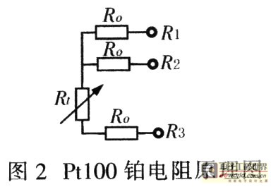
2.2Pt100 principle of platinum resistance temperature controller uses a composite sensor technology, embedded platinum resistance in the temperature package, the principle of wiring as shown in Figure 2. The introduction of the third input line R2 can effectively eliminate the inherent error caused by the resistance of the lead-in line. R1 is the platinum resistance, and R0 is the resistance of the core cable from the outdoors to the main control room (or protection room). Its working principle: The third line R2 forms an equal-arm bridge, eliminating the effects of R0. Therefore, the influence of the internal resistance on the measurement result can only be eliminated when only three core resistors R0 are completely equal.
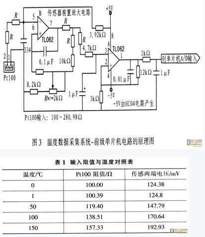
2.3 Introduction to Temperature Data Acquisition System At present, there are two main self-station temperature data acquisition systems: one is the main variable temperature data acquisition system (DW&ZL) embedded in the PST626A main transformer high backup protection, and the other is the main transformer. The temperature data acquisition system is embedded in the CSD12A digital integrated acquisition device in the public screen, as shown in Figure 3. The working principle is that the sensor is connected to Pt100 through a 3.92kΩ resistor through the system's 5V supply. This type of connection usually causes serious non-linear problems, but it is simplified by the software of the post-stage circuit MCU, which simplifies the sensor access method. Follow Pt100 parameters. In the range of 0°C to 150°C, the resistance value is 100 to 157.33Ω. According to the principle of series voltage division, the output voltage is VOUT=VOC/(Pt100+3.92kΩ)×Pt100, and its output voltage is calculated. ,As shown in Table 1.
3. Existing anomalies of temperature measurement system For a certain power supply bureau, there are 36 self-starting stations with 110kV or more self-recovery stations, 4 transformer substations undergoing self-renovation, and 78 main transformers for remote temperature measurement, including 10 330kV transformers. 110kV transformer 68 sets. The 330kV main transformer uses two oil temperature thermometers and one winding temperature meter, and the 110kV transformer uses two oil temperature thermometers. The thermometer needs to output 4 to 20mA current or Pt100 resistance signal, and some of the 330kV transformers also have a remote digital temperature display. The existing abnormal phenomenon of the main transformer temperature measurement system of the self-suppressed transformer station: The first type is the remote digital temperature display (pointer remote temperature meter), the temperature value displayed by the comprehensive back-end machine is inconsistent with the main body thermometer, and the background machine shows two The temperature is also inconsistent, and some differences are larger; the second type is the self-station backstage machine that cannot monitor the temperature; the third type is the centralized control station or the dispatching room cannot monitor the temperature or the deviation is large; the fourth type is that the temperature has ever been normal. The standby chiller is activated, the temperature over-limit alarm, and the main chiller full stop protection malfunction.
4. Solution Based on the above analysis and the routine maintenance and repair practices of the transformer temperature measurement system, the following solutions are targeted:
4.1 Management Measures (1) Settings Management Temperature measurement Many anomalies are caused by fixed setting errors or when parameters are not set. Some integrated self-station temperature plug-ins are embedded in the protection device. Some of the self-station temperature plug-ins are embedded in the common remote control screen. The protection is managed by the construction area. The remote operation is managed by the dispatcher, while the temperature meter is managed by the metering center. The fixed value is set on the spot. Therefore, there are loopholes in management, and it is necessary to re-divide management scope, implement responsibilities, and set unified valuation and setting.
(2) Purchasing management strictly controls the quality of the newly purchased meter and temperature plug-in, and puts forward technical requirements: Newly purchased winding temperature meter, oil temperature meter and temperature transmitter and remote digital display instrument are all required to have a zero adjustment mechanism; Winding temperature meter, oil temperature meter and temperature transmitter and remote digital display unit are all selected from 0 °C ~ 150 °C measurement range: strengthen the first inspection of the newly purchased thermometer to prevent unqualified products from being put into use. The temperature plug-in should have an adjustment function in order to adjust the measurement error caused by the inconsistency of the internal resistance of the external circuit lead-in.
(3)Maintenance and management of all 110kV and above transformer temperature meters must be equipped with a rain cover to prevent rainwater from entering the watch during thunderstorms; strengthen the entire set of acceptance tests for newly commissioned transformer non-power protection, and eliminate the legacy of infrastructure construction. Defects; check the platinum resistance lead wire on both sides of the control cable shield should be reliably grounded; periodic inspection temperature measurement system.
4.2 Exception Handling (1) The first type of abnormal treatment strictly according to the work instructions to replace the damaged temperature package, replace the installation temperature package: Before the installation of temperature package should be filled with transformer oil in the hole, and then slowly insert the temperature Pack and tighten the M27×2 connector, adjust the insertion depth of the thermal package (select the maximum insertion depth possible) and tighten the screws. Ensure that the warm package is completely immersed in oil. The inserting depth of the standard thermostatic bath should not be less than 150mm, to ensure that the warm pack has sufficient insert depth when checking the thermometer on site. Differences in temperature measurement during operation: Measure the resistance between R1, R2, and R3 in segments, compare the causes of the sudden increase in contact resistance, replace the rusted terminals and screws, tighten the screws, and reduce the contact resistance; Or adjust the potentiometer of the temperature plug according to Table 1. If the negative value of the background machine is used, R1 and R2 of the data acquisition system are switched to each other.
(2) The second type of exception handling recalculates and sets the value; replaces the damaged temperature plug.
(3) The third type of exception handling adopts the self-loop form inspection to analyze the specific side of the problem; replace the vulnerable remote plug-in, the modem used in the analog channel, and update the database of the comprehensive self-station; and the processing of the drop frame phenomenon is improved. Baud rate or the original analog replaced with digital channels and other measures.
(4) The fourth type of exception handling strengthens management, including the temperature measurement system into the assessment; the transformer winding temperature is only used for signals, the body oil temperature protection is applied to the signal, the second stage acts on the trip, and the second stage outputs the blocked output ( That is, a pair of temperature output contacts are connected in series in the secondary temperature output circuit); replace the failed meter.
5. Concluding remarks In the transformation and construction of unattended substations, the “four remote” information point-to-point operations are cumbersome and important, and the main transformer temperature information has become an obstacle, and almost every integrated substation has problems. Through the above anomaly analysis and put forward relevant solutions, this problem has been solved, and the transformation process of substations has been accelerated, and at the same time, the actual operating conditions of the transformer can be more accurately reflected, providing real and reliable on-site operation information for monitoring stations and dispatching.


 May 08, 2019