


Please Leave Us A Message
Privacy statement: Your privacy is very important to Us. Our company promises not to disclose your personal information to any external company with out your explicit permission.
 December 02, 2020
introduction
Hand-held electronic devices play an important role in our daily lives. Since reliability is the most important, hand-held devices have adopted prudent engineering design and have adopted lightweight power supplies to ensure reliable use under normal conditions. However, no amount of careful engineering design can prevent them from being “roughly treated” in the hands of users. For example: what happens when a worker in the factory misses a bar code scanner and causes the battery to jump out? Such an event is not predictable by the electronic method, and it does not provide some form of "safety net" (a A short-term power retention system that stores sufficient energy to provide backup power until the battery can be replaced or data can be stored in non-volatile memory. Important data stored in volatile memory will be lost .
Supercapacitors are compact, rugged and reliable, and can support power requirements for back-up systems in the event of a short-term power failure. Similar to batteries, they also require careful charging and power regulation at the output. The LTC®3226 is a two-series supercapacitor charger with a PowerPathTM controller that simplifies the design of the backup system. Specifically, the device includes a charge pump super capacitor charger with programmable output voltage and automatic battery voltage balancing, a low dropout regulator, and a power failure comparator for switching between normal mode and standby mode. . Low input noise, low quiescent current, and compact footprint make the LTC3226 ideal for compact, handheld, and battery-powered applications. This device is available in a 3mm x 3mm 16-pin QFN package.
Backup power application
Figure 1 shows a power retention system using a super capacitor bank that provides a capacity of 165 mW of standby power for approximately 45 seconds without battery power. An LDO is responsible for converting the output of the ultracapacitor bank into a constant voltage supply during standby mode.
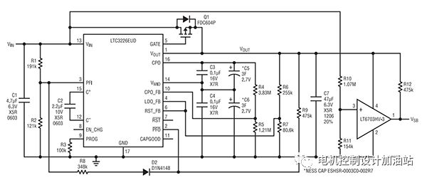
Figure 1: Typical power backup system with supercapacitors
The power backup system can be easily designed with the LTC3226. For example: Take a device with 150mA operating current and 50mA standby current (ISB) when powered from a single Li-Ion battery. To ensure access to a charged battery, the high-level trip point of the power-fail comparator (PFI) is set to 3.6V. When the battery voltage reaches 3.15V, the device enters standby mode; when the battery voltage is 3.10V (VBAT (MIN)), the device enters standby mode, and the time period (tHU) to maintain power is initially set to approximately 45s.
The standby mode trigger level is controlled by an external comparator circuit and the standby mode trigger level is controlled by the PFI comparator. When in standby mode, the device must be disabled from going into full-scale operation to avoid causing the supercapacitor to discharge too quickly.
The design begins by setting the PFI trigger level. R2 is set to 121k. The resistance of R1 should set the PFI trigger level (VPFI) on the PFI pin to 1.2V. The formula is as follows:
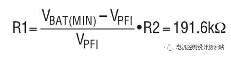
According to this, R1 is set to 191k.
The hysteresis on the VIN pin must be extended to meet the 3.6V trigger level. This can be achieved by adding a resistor-diode series combination between the PFI pin and the PFO pin. VIN(HYS) is 0.5V, VPFI(HYS) is 20mV, and Vf is 0.4V.
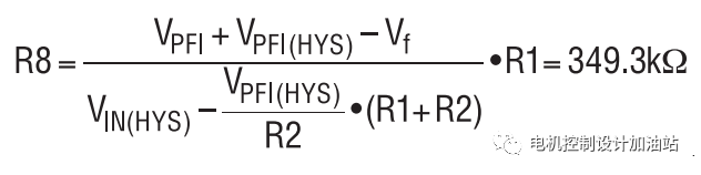
R8 is set to 348k.
By setting R7 to 80.6k and calculating R6 resistance, set the LDO backup mode output voltage to 3.3V. VLDO(FB) is 0.8V.

Set R6 to 255k.
The full charge voltage on the series connected super capacitor is set to 5V. This is done using a voltage divider network located between the CPO pin and the CPO_FB pin. R5 is set to 1.21M and R4 resistance is calculated. VCPO (FB) is 1.21V.
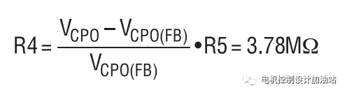
Set R4 = 3.83M.
In standby mode, when the voltage on the ultracapacitor bank begins to approach VOUT, the minimum voltage on the ultracapacitor at the end of the calculated tHU must take into account the ESR of the two supercapacitors and the output resistance of the LDO. Assume that the ESR of each supercapacitor is 100mΩ, while the LDO output resistance is 200mΩ, which will increase VOUT (MIN) by 20mV due to the 50mA standby current. VOUT (MIN) is set to 3.1V to generate a 1.88V discharge voltage (∆VSCAP) on the ultracapacitor bank. Now, you can determine the size of each super capacitor.
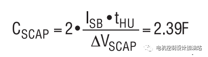
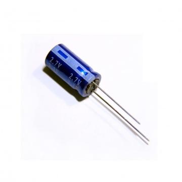
Each supercapacitor was selected as a 3F/2.7V capacitor (ESHSR-0003C0-002R7) supplied by Nesscap. Figure 2 shows the actual backup time of the system with a 50mA load. Since a large 3F capacitor is used in the actual circuit, the backup time is 55.4 s.
in conclusion
High-performance handheld devices require a power backup system that can provide the device with power for a long enough period of time to safely store volatile data when the battery is suddenly removed. Supercapacitors can serve as compact and reliable power supplies in such systems, but they require dedicated control systems for charging and output voltage regulation. The LTC3226 makes it easy to build a complete package by integrating a two-cell supercapacitor charger, a PowerPath controller, an LDO regulator, and a power-fail comparator all in a single 3mm x 3mm 16-pin QFN package. Power backup solution.

Figure 2: Backup time to support 50mA load
The above is the A power retention system using a super capacitor bank we have listed for you. You can submit the following form to obtain more industry information we provide for you.
You can visit our website or contact us, and we will provide the latest consultation and solutions
Send Inquiry
Most Popular
lastest New
Related Products
Send Inquiry
Send Inquiry

Mr. JOHN CHANG
Tel:86-514-87782298
Fax:86-514-87782297
Mobile Phone:+8613375278321
Email:info@stt.tm
Address: 3rd Floor, Weiheng Building No.20 B Area, Yangzhou, Jiangsu,China, Yangzhou, Jiangsu
Related Products List
Mobile Site

Privacy statement: Your privacy is very important to Us. Our company promises not to disclose your personal information to any external company with out your explicit permission.
Fill in more information so that we can get in touch with you faster
Privacy statement: Your privacy is very important to Us. Our company promises not to disclose your personal information to any external company with out your explicit permission.