


Please Leave Us A Message
Privacy statement: Your privacy is very important to Us. Our company promises not to disclose your personal information to any external company with out your explicit permission.
 November 16, 2020
First, the definition of Aluminum Electrolytic Capacitor
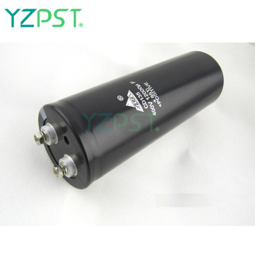
The aluminum Electrolytic capacitor is a capacitor having a positive electrode and a negative electrode. The basic structure of the aluminum Electrolytic Capacitor is composed of an aluminum foil with an anode, a layer of a cathode aluminum foil, a liner paper impregnated with an electrolyte, and a natural oxide film overlaid in a stack. After the electrode is immersed in the electrolyte, the capacitor is closed with an aluminum shell and a plastic cover.

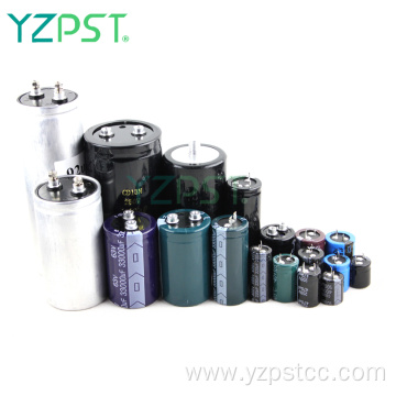
Second, the composition of Aluminum Electrolytic Capacitors
The materials that make up the aluminum electrolytic capacitor are:
Electrolytic paper, electrolyte, anode foil, cathode foil, rubber cover, hose, guide pin and aluminum shell. The core of the aluminum electrolytic capacitor is formed by stacking an anode aluminum foil, an electrolytic paper, a cathode aluminum foil, and an electrolytic paper in order from the inside to the outside, and winding them into a cylindrical shape.


Third, the failure mode
basic concept:
Invalidation: refers to the function of a component losing its original design
Failure mechanism: Physical, chemical, or other causes and processes that cause failure. Such as overload, corrosion, etc. nn failure modes: failure modes, such as open circuit, short circuit, leakage, etc.


Fourth, the life calculation
From the failure mechanism, the use of conditions has a great impact on the life of aluminum electrolytic capacitors. The conditions of use can be divided into environmental conditions and electrical conditions.
The environmental conditions are temperature, humidity, air pressure, vibration, etc. The temperature has the greatest effect on the life. Electrical conditions include voltage, ripple current, and charge/discharge conditions.
1, ambient temperature and life
The influence of the ambient temperature on the lifetime is reflected in the reduction of the capacitance and the increase of the loss tangent. The cause of these phenomena is the gradual diffusion of the electrolyte from the sealing portion to the outside. The relationship between the time variation of the electrical performance and the ambient temperature gives the following formula.
Lx=Lo*BTo-Tx/10
Lo: Rated applied voltage and rated ripple current at the highest operating temperature
Guaranteed life at overlap (hours)
Lx: life expectancy in actual use (hours)
To: The maximum operating temperature of the product (°C)
Tx: ambient temperature in actual use (°C)
B: Temperature Acceleration Coefficient
According to the above formula, when applying an electrolytic capacitor, it is necessary to consider the environmental heat dissipation method, the heat dissipation intensity, the distance between the capacitor and the heat source, and the installation method of the capacitor.

2. Applied voltage and life
SMD, Radial, and Snap-in capacitors for use in most machines, under conditions of use at or below the maximum operating temperature and rated voltage. The effect of the voltage is negligible compared to the effects of acceleration of the ambient temperature and acceleration of the ripple current.
In addition, 350 VDC or more high-voltage products are used in screw-type capacitors used in high-power electronic equipment. Due to the nature of the oxide film (Al 2 O 3 ), which is the conductor of the aluminum electrolytic capacitor, the value of the applied voltage value is not higher than the rated voltage. Will affect its life.
3, ripple current impact life
Ripple current calculation is an important parameter to obtain the power loss of the capacitor. When designing the circuit to select the capacitor, we must first determine the magnitude of the current ripple, which is related to the design specifications and the specific topology. Aluminum electrolytic capacitors are often used after the rectifier module with a stable voltage. After selecting a specific topology, we obtain the minimum capacitance according to the specifications. In the choice of ripple current, derating design is needed.

The capacitance required to control a ripple voltage is:

Due to the large loss of aluminum electrolytic capacitors compared to Other Capacitors, ripple currents can cause internal heating. The heat generated by the ripple current will increase the temperature, so it has a great impact on product life. In this way, the maximum allowable ripple current value must be set in advance according to different products. The degree of heat of the applied ripple current can be calculated by the following formula.
W=Ir2*ESR+V*IL
W: internal power consumption
Ir: ripple current
ESR: Internal Resistance (Equivalent Series Resistance)
V: Applied voltage
IL: Leakage current
At the highest operating temperature, the leakage current increases to 5 to 10 times at 20°C but still Ir ≥ IL, then W= Ir2·ESR. Requirements for internal heat and heat to reach equilibrium conditions, then
Ir2·R=β*A*ΔT
β: heat release constant
A: Shell surface area (m2)
A=π/4·D(D+4L)
D: diameter of the shell (m)
L: length of shell (m)
ΔT: Temperature rise due to ripple current (°C)
| Then, the internal heating ΔT = | Ir2·ESR |
| β*A |
In addition, the heating of the ripple current at 120Hz can be obtained by (7):
| △T= | Ir2·ESR | = | Ir2·tanδ | |
| βA | βAωC |
| (here ESR= | Tan δ | ) |
| ωC |
Tanδ: loss at 120Hz
ω : 2πf (f equals 120Hz)
C: Capacitance at 120Hz (F)
The ESR value varies according to the temperature change. Therefore, the correct ΔT is required to actually measure the value of the thermocouple.
Taking into account the effects of internal heating due to ripple currents and ambient temperature, the NIPPON-CHEMICON life presumption is:
a) The guaranteed lifetime when DC nominal voltage is applied is
| Lx=Lo×2 | To-Tx | ×2 | -△T | |
| 10 | 5 | |||
··············································
b) The guaranteed lifetime when the ripple current is allowed to overlap is
| Lx=Lr×2 | To-Tx | ×2 | △To-△T |
| 10 | 5 | ||
·········································································································基板
C)
| Lx=Lr×2 | To-Tx | ×2 | -2+(25-△T)/b |
| 10 | |||
···················································································· screw terminal
Lr: Guaranteed life at nominal operating current at the maximum operating temperature (hours)
Lx: actual life hours
To: The maximum operating temperature of the product (°C)
Tx: ambient temperature in actual use (°C)
T: The degree of heat generated by the core of the core caused by the ripple current (°C)
To: The degree of heat generated by the center of the core when the allowable ripple current is applied (°C)
(△T o=5°C for the maximum use temperature 105°C series)
※ Note about TX (ambient temperature at the time of actual use)
In the accelerated temperature test, confirm that the 10°C 2-fold criterion is within the range of 40°C to the maximum operating temperature.
It can be seen from the measurement results of products returned from the market that the 20°C to 25°C range can be studied using the 10°C 2x rule. However, the environmental conditions in the application are mostly unclear. Therefore, if the temperature is 40°C or less, please use it as 40°C. Life prediction.
※Note about ΔT (Ripple current causes core center heating)
The ambient temperature + ripple current causes the core center heating threshold
Examples of thresholds for core heating at various temperatures
| Ambient temperature (°C) | 40 | 55 | 65 | 85 | 105 |
| ΔT(°C) | 30 | 30 | 25 | 15 | 5 |
Namely: The maximum operating temperature is 105°C. The highest ripple current generated when the series is at a maximum operating temperature of 105°C reaches the maximum limit of 5°C (total 110°C), and the maximum ripple current produces a heat of 25°C at an ambient temperature of 65°C. (Total 90°C), the lifetime of the two cases is the same.
The value of the self-heating of the ripple current is required to measure the temperature at the center of the capacitor core and the temperature around the capacitor with a thermocouple. The difference between the two is the value of the self-heating of the ripple current. The value thus obtained is The most correct. However, since it is very difficult to measure the temperature inside the capacitor in an actual machine, the temperature of the side surface of the capacitor case is first measured, and the temperature at the center portion of the core is estimated by using the temperature difference coefficient described below.
Temperature difference coefficient of different shell diameters
| Capacitor outside diameter ΦD(mm) | 5 | 6.3 | 8 | 10 | 12.5 | 16 | 18 | twenty two | 25 |
| Temperature difference coefficient | 1.1 | 1.1 | 1.1 | 1.15 | 1.2 | 1.25 | 1.3 | 1.35 | 1.4 |
| Capacitor outside diameter ΦD(mm) | 30 | 35 | 40 | 50 | 63.5 | 76 | 89 | 100 | |
| Temperature difference coefficient | 1.5 | 1.65 | 1.75 | 1.9 | 2.2 | 2.5 | 2.8 | 3.1 |
If you need to make more accurate life predictions, use actual measured values. In addition, the self-heating value ΔT produced by the ripple current can also be calculated by Equation (12). Maximum operating temperature, most series ΔT0=5°C. For other series please refer to the supplier information.
ΔT=(IX/I0)2×ΔT0...............(12)
I0: frequency-corrected rated ripple current (Arms) at the highest operating temperature
IX: Ripple current (Arms) in actual use
* When the frequency of the commercial power supply of the aluminum electrolytic capacitor in the switching power supply overlaps with the switching frequency component, the internal power consumption is as shown in the following equation.
W=I(f1)2*ESR(f1)+I(f2)2*ESR(f2)+...+I(fn)2*ESR(fn)
W: power consumed
I(f1), I(f2)...I(fn): Ripple current values at various frequencies (Arms)
ESR(f1), ESR(f2)... ESR(fn): Equivalent series resistance values (Ω) at various frequencies
Let the frequency correction coefficient at each frequency be F(fn), where f0 is the frequency at which the ripple current is referenced. Let ESR(fn) = ESR(f0)/F(fn)2 be established; use the following formula to convert each The ripple current value of the frequency component is the reference ripple frequency effective value (f0)
I(f0)=√{{{I(f1)/F(f1)}2+{I(f2)/F(f2)}2 +...{I(fn)/F(fn)}2}]
I(f0): Reference frequency ripple current value (Arms)
F(f1), F(f2)... F(fn): frequency correction coefficients for various frequencies f1 f2... fn
In general, the rated ripple current value is normalized by a sine wave effective value of 120 Hz. The internal resistance (ESR) maintains the frequency characteristics, allowing ripple current values to change depending on the frequency.
(Example) Example of frequency correction factor (radial high frequency low resistance KZE series from manufacturer CHEMICON)
| Nominal capacitance (μF) | Frequency (HZ) | 120 | 1K | 10K | 50-100K |
| 180μF or less | Frequency correction factor | 0.40 | 0.75 | 0.90 | 1.00 |
| 220~560μF | 0.50 | 0.85 | 0.94 | 1.00 | |
| 680~1800μF | 0.60 | 0.87 | 0.95 | 1.00 | |
| 2200~3900μF | 0.75 | 0.90 | 0.95 | 1.00 | |
| 4700μF or more | 0.85 | 0.95 | 0.98 | 1.00 |
Example of Frequency Correction Factor (Manufacturer CHEMICON's snap-in SMQ Series)
| Nominal capacitance (μF) | Frequency (HZ) | 50 | 120 | 300 | 1K | 10K | 50-100K |
| 4.7μF or less | Frequency correction factor | 0.65 | 1.00 | 1.35 | 1.75 | 2.30 | 2.50 |
| 10~68μF | 0.75 | 1.00 | 1.25 | 1.50 | 1.75 | 1.80 | |
| 100~1000μF | 0.80 | 1.00 | 1.15 | 1.30 | 1.40 | 1.50 | |
| 200μF or more | 0.85 | 1.00 | 1.03 | 1.05 | 1.08 | 1.08 |
4. Other factors affecting life expectancy
The electrolytic solution of the aluminum electrolytic capacitor diffuses outward through the sealing portion, and the resulting gradual failure is an important factor in determining the length of life. The reasons for accelerating this phenomenon include the following two reasons besides the aforementioned ambient temperature and ripple current.
4.1 Overvoltage
If an overvoltage exceeding the rated voltage is continuously applied, the leakage current of the product rapidly increases. Heat leakage and gas generation due to leakage currents cause the internal pressure to rise. This reaction can be accelerated by the applied voltage, the current capacity of the power supply, and the increase in the ambient temperature, sometimes causing the pressure valve to loosen or be damaged. Even if no abnormality occurs in the appearance of the capacitor, the life of the capacitor can be shortened.
When the capacitors are used in series, the leakage current deviates from the partial pressure and becomes uneven. Individuals can easily apply an overvoltage. In this case, measures such as selecting an unbalanced rated voltage or connecting a voltage equalizing resistor must be taken.
Recommended voltage balance resistor selection: R = VW / 3I leakage current
At present, due to energy-saving requirements, the selection of the resistance value of the voltage equalization resistor is increasing, and the requirements for the consistency of the capacity and leakage current of the capacitor are increasing.
4.2 Reverse voltage
When a reverse voltage is applied and the voltage is applied to the cathode foil without chemical film formation, the conductor oxide film is forcibly formed. This causes the same heat generation and gas generation as in the case of an overvoltage, resulting in drastic reduction in the capacitance and the loss angle. Increase.
Cathodic reaction: 4OH- - 4e = 2H2O + o2 + heat
3O2 + 4Al = 2Al2O3
Anode reaction: 2H+ + 2e = H2
Reverse voltage, reverse current is too large, along with gas generation, anode foil and pressure valve are damaged. If the pressure valve is too late to open, it will explode.
4.3 Charge and Discharge
The general product is used in a power supply circuit of a frequent strobe flash lamp, a charging/discharging circuit of a riveting machine, and an AV apparatus having a large output, and the cathode foil is formed by the discharge current, and the capacity is drastically reduced. There is also the generation of internal heat generation and gas generation when the cathode foil is formed, which may cause the pressure valve to loosen or be damaged. The higher the temperature, the lower the discharge resistance, the greater the applied voltage, and the faster the charge/discharge frequency, the faster the product will deteriorate.
In general, when an aluminum electrolytic capacitor is placed in a vigorous charge/discharge circuit, the cathode foil is formed into a film due to discharge after charging, and the capacity is rapidly reduced. When the cathode side and the anode side are short-circuited, the charge originally stored on the anode side is instantaneously moved to the side of the cathode foil. At this time, the voltages of the two side foils are equal, and the side of the cathode foil is gradually formed. This is the same as applying the reverse voltage.
1. Normal charge status
2. When the power supply V1 is disconnected and discharged, the charge on the anode foil side will move to the cathode foil side. Since the overall charge amount is constant, that is, Q=C+·V2+C-·V2,
C+·V1=C+·V2+C-·V2
| V2= | C+·V1 | |
| C++ C- |
In the case of 16V10000μF, the externally applied voltage is assumed to be 13V, and if the capacitor size is φ50×80L, the anode foil is 5.3μF/cm2, and the cathode foil is 100μF/cm2, then
V2=5.3*13/(5.3+100)=0.65(V)
If a Φ35×50L size capacitor is manufactured, the anode foil must use a high-magnification foil, the anode foil is 11.5 μF/cm2, and the cathode foil is 100 μF/cm2.
V2 = 11.5 × 13 / (11.5 + 100) = 1.34 (V)
Therefore, when a high-rate anode foil is used, a higher voltage is generated at the cathode foil during discharge, and the cathode formation reaction is accelerated, resulting in heat generation and pressure valve loosening. In the case of miniaturization, measures such as the use of a high-rate cathode foil or a cathode foil with an oxide film have been taken.
4.4 Pulse current
If the operation is repeated frequently, the situation is the same as when the ripple current is applied, and the degree of heat generation of the core exceeds the permissible value. An abnormal heat is generated at the connecting portion of the external terminal and the connecting portion between the lead wire inside the capacitor and the foil, which requires attention.
4.5 for AC circuits
If an aluminum electrolytic capacitor is used in an alternating current circuit, rapid gas generation inside the capacitor is accompanied by heat generation and an increase in internal pressure, which further causes the pressure valve to act, leaking electrolyte from the seal, and sometimes causing the worst case. Explosions, scattered combustibles, and sometimes short circuits. Therefore, please do not use it in AC circuits.
V. Other methods for estimating the life of aluminum electrolytic capacitors
The general steps of capacitor life estimation, of course, if we have already designed the product, we also have a way to estimate the life of the capacitor, that is, there is already a product. Let's check if the design of the capacitor life is reasonable, we can test the temperature of the capacitor center point , and then through the capacitor life calculation formula to test.
The above is the Aluminum electrolytic capacitor definition and composition we have listed for you. You can submit the following form to obtain more industry information we provide for you.
You can visit our website or contact us, and we will provide the latest consultation and solutions
Send Inquiry
Most Popular
lastest New
Related Products
Send Inquiry
Send Inquiry

Mr. JOHN CHANG
Tel:86-514-87782298
Fax:86-514-87782297
Mobile Phone:+8613375278321
Email:info@stt.tm
Address: 3rd Floor, Weiheng Building No.20 B Area, Yangzhou, Jiangsu,China, Yangzhou, Jiangsu
Privacy statement: Your privacy is very important to Us. Our company promises not to disclose your personal information to any external company with out your explicit permission.
Fill in more information so that we can get in touch with you faster
Privacy statement: Your privacy is very important to Us. Our company promises not to disclose your personal information to any external company with out your explicit permission.