


Please Leave Us A Message
Privacy statement: Your privacy is very important to Us. Our company promises not to disclose your personal information to any external company with out your explicit permission.
 December 15, 2020
2012 is the first year that LEDs have entered indoor and home lighting on a large scale, and it is also the first year for civilian LEDs. As a civilian product, more stringent requirements are imposed on the performance, price and reliability of the product. On the one hand, it is required that the luminous efficiency of LEDs is continuously improved and the price is continuously lowered. On the other hand, there are many requirements for the constant current driving source of the LED. In the eyes of ordinary people, the life of LED itself is already very high, but the actual life is very low, often caused by low power supply life. The life of a power supply often depends on the life of the Electrolytic capacitor. Because the life of electrolytic capacitors is generally considered to be very low. If the constant current source does not have an Electrolytic Capacitor at all, its lifetime can be very high. Moreover, the power factor can be improved after the electrolytic capacitor is removed. Therefore, a variety of constant current sources of electroless capacitors attract a lot of attention.
A simple method of electroless capacitor
It is easy to remove the electrolytic capacitor, and it can work.

Figure 1. The simplest electroless capacitor circuit
However, the life of such a circuit is shorter because it does not use a constant current measure, so when the input voltage rises or the temperature rises, the current rises rapidly, so that the LED is burned soon. Although the resistor current limiting can solve some problems, its efficiency is only 52%-73%. It is totally unacceptable.
Therefore, constant current must be applied, even the simplest constant current diode.
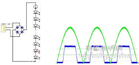
Figure 2. Electroless capacitor circuit and current waveform with constant current diode
However, this circuit is also inoperable. Because the input is half a sine wave, the LED can't start at low voltage. Although the voltage can rise to a certain level, it can be constant current. At this time, the current waveform is close to a rectangular wave, so its power factor is not amazing. Satisfactory, because the power factor can be equal to 1 only when the current waveform is the same as the voltage waveform. So can you develop a circuit that makes its current waveform as close as possible to the voltage waveform?
2. ExClara's EXC100 solution
ExClara in Silicon Valley, USA, proposed a solution that would solve this problem in close proximity. Since the current can only be flat after using a constant current diode, it is only possible to use a staircase wave to approach the sine wave.

Figure 3. Using a rectangular wave to approximate a sine wave and a measured map
This seemingly simple thing, really to achieve is a very complicated matter. In order to obtain such a current waveform, it is necessary to sequentially turn on the LED strings having different constant current values. The specific block diagram of its EXC100 chip is shown in Figure 4.
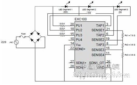
Figure 4. Connection diagram of the EXC100
It first measures the input voltage. After the input voltage reaches a certain value, it starts to turn on the first string of constant currents at a lower value. After reaching a higher voltage, it starts to connect the second string after the first string. The LED is constantly flowing at a higher current; finally, after the voltage is higher, the third string of LEDs is turned on and the current is constantly flowing to a higher value. So its internal structure is very complicated.

Figure 5. Block diagram of CL8801
In fact, there is no circuit for measuring the input voltage. This circuit measures the input voltage and compares it with several set values, and turns on the switches 1, 2, 3, and 4 in turn. These switches must be high voltage resistant MOS tubes. Therefore, the entire chip must be fabricated using a high-pressure process. The cost is very high. The price of the EXC100 is about RMB 10.
AIC in Taiwan has also made similar products.

There are also many companies in South Korea, Japan, etc. that have similar products. It seems that this product is very popular, and the cost is relatively high.
3. Jingfeng's BP5801
In order to reduce costs, the easiest way is to take the internal high-voltage MOS switch tube to the outside and use discrete components. Jingfeng's BP5108 uses this method (Figure 6).

Figure 6. BP5108 connection diagram
At 220V, when the rectified voltage rises to 104.7V, the first string of 40 LEDs starts to conduct (the voltage is 134V); when the voltage increases by 34.89V, the second string of 23 LEDs starts and the first string of LEDs Connected in series and turned on (its voltage is 76V); when the voltage is increased by 25.21V, the third string of 23 LEDs is connected in series and turned on (the voltage is 76V), and the last three strings are led by the maximum current of 30.8mA. Pass (rated current is 20mA). Because the current waveform is closer to the sine wave and is in phase with the voltage waveform, the power factor can be as high as 0.968 and the efficiency can be 90.6%.
The detailed circuit diagram is shown in Figure 7. The first three (two protections, one rectifier bridge) are common, one inductor and one capacitor are the filters needed to reduce electromagnetic interference EMI, because this linear constant current source becomes a switch type. In addition, the latter 11 resistors, three capacitors and three MOS tubes, a total of 22 components, and MOS tube needs to use 2N60, is also a large and expensive device.

Figure 7. BP5108 specific circuit diagram
4. The gains and losses of the linear constant current source without electroless capacitor
This type of electroless capacitor has a linear constant current source value, so the electrolytic capacitor is removed for two reasons:
1. The short life of electrolytic capacitors is actually a misunderstanding of the average person. Of course, this misunderstanding is also obtained from a large number of examples. The main reason is that the Chinese market is full of inferior electrolytic capacitors, which have a very short life. But this does not mean that all electrolytic capacitors have a short life.
There are two types of electrolytic capacitors, one is a liquid electrolyte and the other is a solid electrolyte. Liquid electrolytic capacitors have a short life span because of the drying up of liquids. Therefore, new long-life electrolytic capacitors use solid electrolytes. The life of solid electrolytic capacitors is said to be 23 years, far exceeding the life of LEDs. However, the price of solid electrolytic capacitors is relatively expensive.
So isn't liquid electrolytic capacitors able to achieve long life? This is not the case. The industry knows that the life of Japanese ruby electrolytic capacitors can reach 10,000 hours at 105 °C, and the life is doubled for every 10 degrees decrease in temperature. It can have 40,000 hours at 85 degrees Celsius and 80,000 hours at 75 degrees, which can fully meet the needs of LEDs. And the price is not expensive to an unacceptable level. Recently, Ruby has developed a small-volume LLE series electrolytic capacitor that doubles its lifespan, and its life at 105 °C is up to 20,000 hours, which is specially used for small-volume bulbs. Moreover, there are already manufacturers in the country that can produce liquid electrolytic capacitors comparable to rubies.
Therefore, the life of electrolytic capacitors is not a problem.
2. Power factor cannot be increased after adding electrolytic capacitor
First let us look at the national regulations: According to the draft of China's indoor lighting LED bulb standard, the power factor should not be lower than 0.75, but in the general specification of LED driving power supply for lighting, <5W, not required, 5W-25W, The first level is >0.85 and the second level is >0.7. The US Energy Star does not require a <5W bulb, but requires PF>0.7 for >5W LED lamps (ANSIC82. 77-2002LM -79-08), 03 /22/2010. Therefore, below 5W, there is no requirement for power factor. I also want to say a few fair words here. Our country does not require power factor for energy-saving lamps below 15W, but only above 15W.
In fact, the power factor should also be seen as capacitive or emotional. Usually, the home and residential areas are mainly sensible, because many white goods like refrigerators, washing machines, and air conditioners have motors, which are all inductive loads; even black appliances such as TVs and stereos have transformers, which are also inductive loads. As for fluorescent lamp ballasts and electronic ballasts in energy-saving lamps, they are also inductive loads. Electrolytic capacitors are capacitive loads and they can be compensated. From this point of view, for LED lamps using electrolytic capacitors, the state should not only limit the power factor when formulating standards, but should also encourage and reward it.
In any case, because LED bulbs are mainly used to replace incandescent lamps. The most commonly used incandescent lamps are 40W and 60W. According to the current LED luminous efficiency, the 5W LED bulb can replace the 40W incandescent lamp. After 1-2 years, the 5W bulb can also replace the 60W incandescent lamp, so for LED bulbs, the power factor is not a problem at all. Moreover, even with electrolytic capacitors, it is easy to increase the power factor to 0.7 or more by limiting the charging current.
It can be seen that the use of electrolytic capacitors is not a problem, regardless of life or power factor.
So what are the problems and shortcomings after removing the electrolytic capacitors like the previous methods? Some:
1. The electroless capacitor solution will bring flashing of the light. We know that the LED will only emit light when there is current flowing, and it can be seen from the current waveform diagram in Figure 3 that its illumination is intermittent with double the power frequency (bridge rectification). It is 100Hz in China and 120Hz in the United States. The highest flicker frequency that humans can feel is 70 Hz. This kind of flicker, although not visible to the human eye, does not mean that it is not harmful to humans.
According to reports, the main obstacles are dizziness, eye strain, and migraine can increase the risk of stroke.
In addition, this flickering also has a flashing effect, and multiple images of moving objects appear during photography, which may result in the loss of important images in the security camera. Customers who use them domestically have reflected such problems.
2. Since the LED is not continuously turned on, especially the third string is turned on only for a short time, and the current during turn-on exceeds the rated value by more than 54%. This kind of work will bring two problems. One is that the utilization rate of LED is not high, which will reduce the light efficiency of the whole lamp. The author has personally tested the same luminous efficiency and the same number of LEDs, one using the above-mentioned electroless capacitor. The constant current source and the other use a linear constant current source with electrolytic capacitors. As a result, the overall lighting efficiency of the former is 15% lower than that of the latter (both tested with an integrating sphere without a lampshade). Another problem is that its maximum current exceeds the rated current by 54%. Although it is a short time, the cumulative operation for a long time may reduce the life of the LED. Because the maximum current specified by the LED can only be 16%-25% higher than the rated current.
3. Due to the use of switching, the characteristics of the non-electromagnetic interference of the linear constant current source are lost. Even add an electromagnetic interference filter. The measured results of the electromagnetic interference of the EXC100 are shown in Figure 8. The blue line in the figure is the standard of the US FCC Class B, although its test results are able to meet the standard. However, as a linear constant current source, there should be no interference at all, and there is no need to do testing at all. Now it is necessary to test to see if it can meet the standard. This cannot be regarded as an advantage anyway.
In addition, due to the serious distortion of the waveform, its harmonic distortion is also serious. For example, the harmonic of BP5108 is as high as 25.6%.

Figure 8. Electromagnetic interference of EXC100
Finally, the last "advantage" of this type of drive power supply is also mentioned. It is possible to connect to a thyristor dimmer. Because thyristor dimmers require a purely resistive load, and now with so many measures of this type of drive power, the power factor is close to 1, which can of course be connected to a thyristor dimmer. So is this an "advantage"? It should be known that after using the thyristor dimmer, the power factor and efficiency of the whole system will become very poor, so it takes so much effort to improve the power factor of the driving power supply. And efficiency is not all in vain? If it is really necessary to dim, the LED can be dimmed with DC or pulse width modulation (PWM), which can really achieve efficient and energy-saving dimming. It is completely unnecessary to adopt the thyristor technology decades ago.
V. Conclusion
In fact, the LED is a DC device, preferably powered by DC. The electrolytic capacitor is also the best way to use its energy storage effect to turn a half sine wave into near DC. As long as the electrolytic capacitor is used, the above problems do not exist. As for the power factor, it is not a problem. The fluorescent lamps that have been widely used in our country and the energy-saving lamps that have been promoted recently have never mentioned the power factor requirement. Moreover, the capacitive power factor is the best compensation for a large number of inductive power factors. If it is really required that the power factor should satisfy a certain value, it is also possible to add a few components in the case of using an electrolytic capacitor.
The above is the Pros and cons of electroless capacitor linear constant current source we have listed for you. You can submit the following form to obtain more industry information we provide for you.
You can visit our website or contact us, and we will provide the latest consultation and solutions
Send Inquiry
Most Popular
lastest New
Send Inquiry
Send Inquiry

Mr. JOHN CHANG
Tel:86-514-87782298
Fax:86-514-87782297
Mobile Phone:+8613375278321
Email:info@stt.tm
Address: 3rd Floor, Weiheng Building No.20 B Area, Yangzhou, Jiangsu,China, Yangzhou, Jiangsu
Related Products List
Mobile Site

Privacy statement: Your privacy is very important to Us. Our company promises not to disclose your personal information to any external company with out your explicit permission.
Fill in more information so that we can get in touch with you faster
Privacy statement: Your privacy is very important to Us. Our company promises not to disclose your personal information to any external company with out your explicit permission.