


Please Leave Us A Message
Privacy statement: Your privacy is very important to Us. Our company promises not to disclose your personal information to any external company with out your explicit permission.
 May 20, 2019
"Switching transformer" generally refers to the transformer used in "switching power supply". When working in a pulse state of a frequency of ten to several tens of kilohertz or even hundreds of kilohertz, the iron core is generally made of ferrite material. The switching power supply transformer is a Power Transformer with a switching tube. In addition to the voltage conversion function of the ordinary transformer, the circuit also has the functions of insulation isolation and power transmission, which are generally used in switching power supplies and the like involving high frequency circuits.
Switching transformer parametersVoltage ratio : refers to the ratio of the primary voltage of the transformer to the secondary voltage.
DC resistance : that is, copper resistance.
Efficiency : output power / input power * 100 [%].
Insulation resistance : The insulation capability between the windings of the transformer and between the cores.
Electric strength : The degree to which the transformer can withstand the specified voltage within 1 or 1 minute.
Switching power supply transformer winding method1. Main output magnetic core transformer B1 winding method main output magnetic core transformer B1 winding method
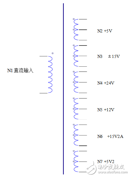
Transformer B1 winding connection diagram
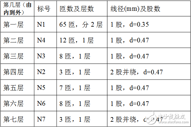
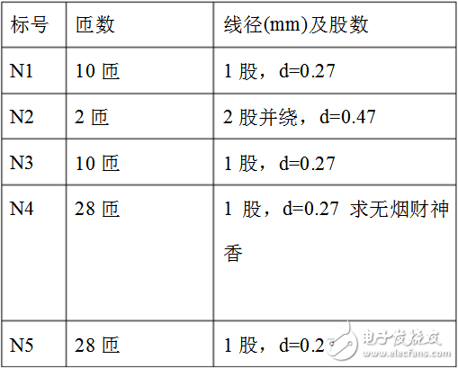
Winding method: (from inner layer to outer layer order) (core without air gap)
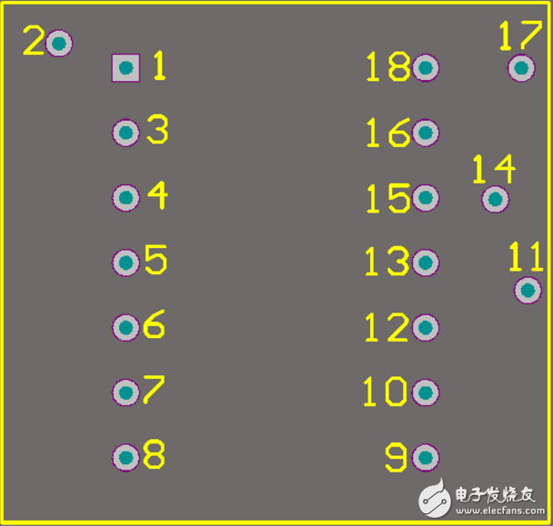
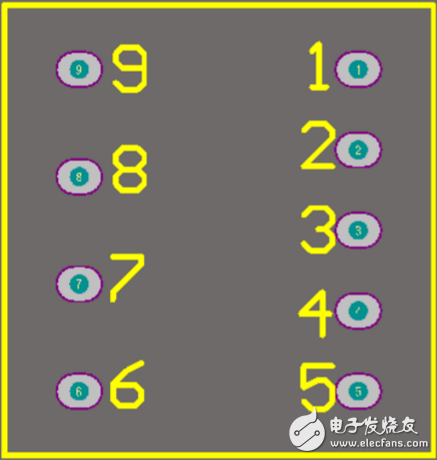
Transformer B1 pin diagram
Pay attention to the problem of the same name when winding. First, lay a layer of insulation on the column in the skeleton and start winding. N2, N3, N4 have different voltages, which can be wound around the same layer, separated by a distance, and covered with insulating paper. Other non-common ground windings are separated by three layers of insulation, and finally three layers of insulation are outsourced.
Due to the different winding winding methods and processes, the output voltage may be slightly deviated. The output voltage can be adjusted in a small range by adjusting the magnitude of the dummy load resistance around the parameters given in the component table.
2. Driving magnetic core transformer winding method
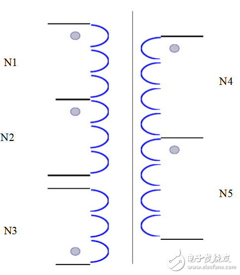
Transformer B2 winding connection diagram
Winding method: (from inner layer to outer layer order) (core without air gap)
Transformer B2 pin diagram
The above is the Switching transformer parameter_switching transformer winding method we have listed for you. You can submit the following form to obtain more industry information we provide for you.
You can visit our website or contact us, and we will provide the latest consultation and solutions
Send Inquiry
Most Popular
lastest New
Send Inquiry
Send Inquiry

Mr. JOHN CHANG
Tel:86-514-87782298
Fax:86-514-87782297
Mobile Phone:+8613375278321
Email:info@stt.tm
Address: 3rd Floor, Weiheng Building No.20 B Area, Yangzhou, Jiangsu,China, Yangzhou, Jiangsu
Related Products List
Mobile Site

Privacy statement: Your privacy is very important to Us. Our company promises not to disclose your personal information to any external company with out your explicit permission.
Fill in more information so that we can get in touch with you faster
Privacy statement: Your privacy is very important to Us. Our company promises not to disclose your personal information to any external company with out your explicit permission.